

Tips for Slave Board BMS Matching and Wiring
, by MAXKGO COMPANY, 5 min reading time
, by MAXKGO COMPANY, 5 min reading time
Hey guy, welcome to this blog.
This blog will show you how to wire battery packs with different numbers of strings when using the master-slave board BMS.
We are actively collecting customer feedback during pre-sales and after-sales work, and we have observed that some users are not very clear about the way of shorting the wiring sequence. We will demonstrate and explain the operation through this blog.

MAXKGO’s master-slave board BMS can be used with 6S-35S battery packs. If customers don’t know how to match them (Or there are other requirements: for example, there are requirements for the number of temperature sensors), please contact us through social media or email: info@maxkgo.com, our staff will provide matching schemes and make corresponding wiring diagrams according to your needs.

LTC6811-12S slave boards have 5 temperature sensing interfaces (4 NTC temperature sensors can be connected externally).
LTC6812-15S, LTC6813-18S slave boards have 9 temperature sensing ports (8 NTC temperature sensors can be connected externally).
Principle for picking slave boards: The more average of battery cells connected to each slave board the better. For example, for a 27S battery, the combination of 14S+13S is better than the connection of 12S+15S.
For uneven cell count in series, only the last slave board in the daisy-chained loop should have one cell less connected than the other slaves. Ex: 29S=10S+ 10S+9S / 29S=15S+14S
Let's take a look at a few common collocations, and you will have a better understanding of the collocation of slave boards:


We used 30S battery pack to show how to used connect the wire to 3*12S LTC6811 slave board BMSs
Items we used:
30S 1P battery pack
3* HY2.0 single head 13P lines
For a complete master-slave board wiring tutorial, please refer to the blog "MAXKGO master-slave board BMS installation tutorial"

Refer to the wiring diagram for operation:
 It can be seen from the wiring diagram that the last three lines of each group of cables will be short-circuited. Next, we will show you the operation steps in the form of pictures.
① Solder the ground wire (black wire) of the first group of HY2.0-13P lines to the negative pole of the battery pack.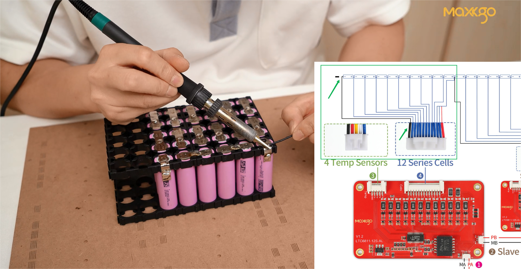
② Solder the bule wires 1-9 of the first slave board to the battery cells 1-9 respectively.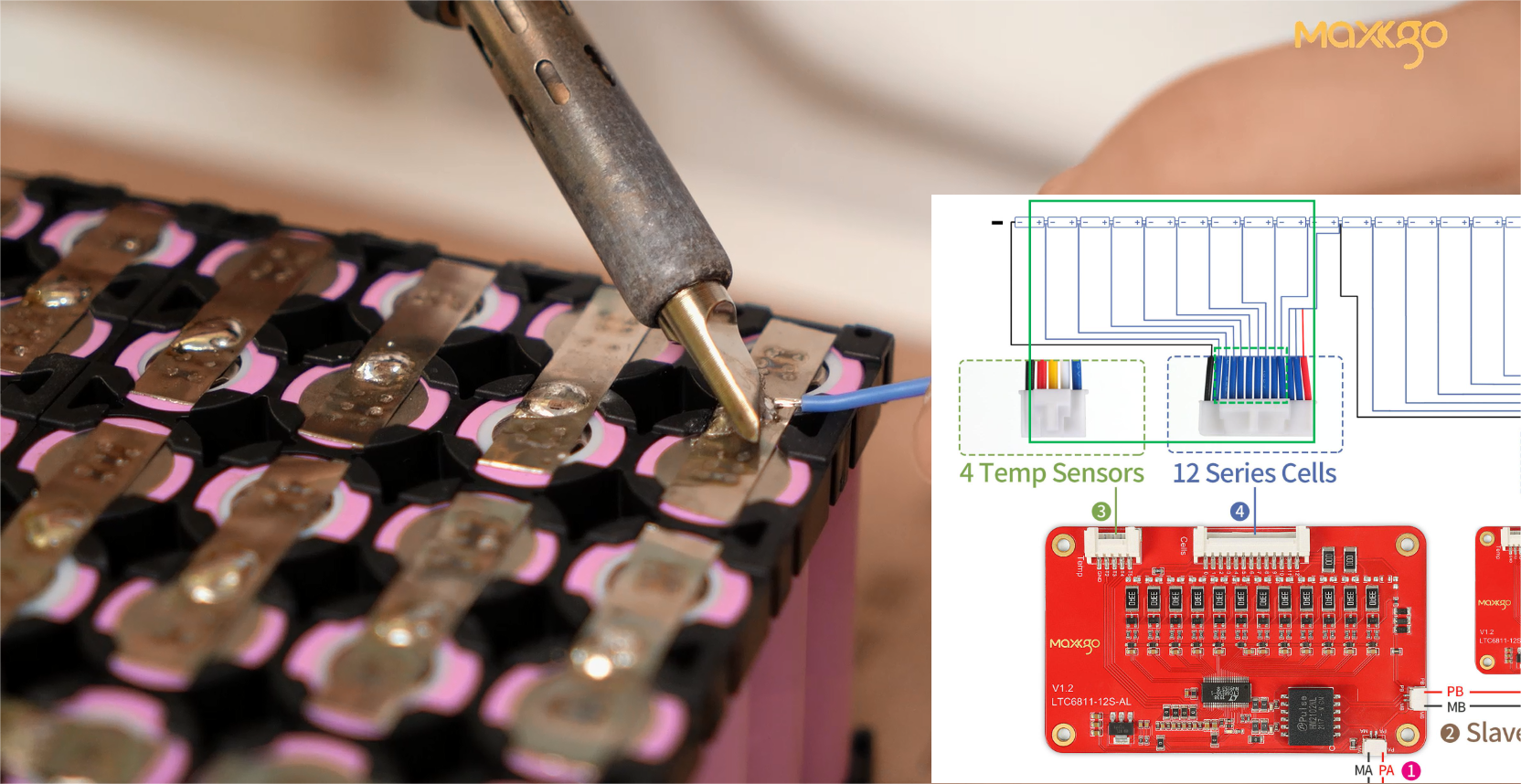
③ Since we only connect 10 batteries to the first slave board, the blue wires 10, 11 and the red wire 12 need to be shorted to the 10th battery cell.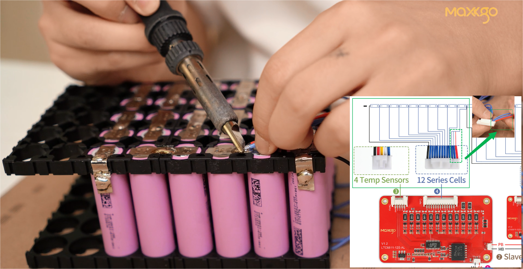
④ The ground wire (black wire) of the second group of HY2.0-13P lines needs to be soldered to the same battery (the 10th battery).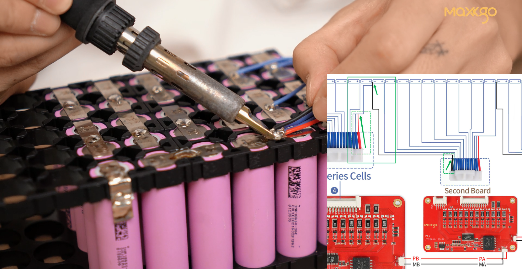
⑤ Solder 11-19 batteries with the 1-9 blue wires of the second group of HY2.0-13P lines according to battery arrangement.

⑥ Since we only connect 10 batteries to the 2nd slave board, the blue wires 10, 11 and the red wire 12 of the second group of HY2.0-13P lines need to be shorted to the 20th battery cell.

⑦ The third group of HY2.0-13P lines is also soldered according to the same steps.
- The ground wire (black wire) of the third group of HY2.0-13P lines needs to be soldered to the same battery (the 20th battery).
- Solder 21-29 batteries with the 1-9 blue wires of the third group of HY2.0-13P lines according to battery arrangement.
- Since we only connect 10 batteries to the third slave board, the blue wires 10, 11 and the red wire 12 of the third group of HY2.0-13P lines need to be shorted to the total positive pole of the battery pack.
Up to this step, the soldering of three sets of HY2.0-13P lines has been completed.
Item we used: multimeter * 1
Measure whether the voltage of each battery wire is consistent with the total voltage.
Through this part, you can check whether there is a welding error


After the battery voltage measurement is correct, solder the battery pack connection cables.

Turn on the switch button, the display will show data, and the installation is complete.

Error 18 will appear when booting for the first time, which is a normal phenomenon. After the display goes off, press the power button to start the device normally. The above is an operation demonstration on how to solder the wires from the slave board BMS. The focus of the operation is the welding of the ground wire and the shorting of the redundant cable.
We also made a vedio about this blog. After you watch it, consider subscribing to the MAXKGO channel for more BMS videos.
Here is the video link: https://youtu.be/XDO81Ag-czM
Because MAXKGO master-slave board BMS can customize different solutions according to customer needs.
You are welcome to contact us via social media or email: info@maxkgo.com, our staff will match the scheme and make the corresponding wiring diagram according to your needs.
We look forward to hearing from you.
Thank you for your patience in reading, see you in the next blog.
Please follow our social media for more info, thanks.
YouTube: https://www.youtube.com/@MAXKGO
Instagram: https://www.instagram.com/maxkgo_share/
Facebook: https://www.facebook.com/MaxkgoMall


