
MAXKGO master-slave board BMS installation tutorial
, by MAXKGO COMPANY, 7 min reading time
, by MAXKGO COMPANY, 7 min reading time
Hi, guy. Welcome to this blog. This blog will introduce the complete installation process of MAXKGO master-slave board BMS wiring and parameter adjustment in detail.
For all of you who don't like reading, we've made a video about MAXKGO master-slave BMS installation. After you watch it, consider subscribing to the MAXKGO channel for more BMS videos.
Here is the video link : https://youtu.be/p1ryD3uqHew
For this installation we use:
1 * Step-down Power Supply Module 12V
These four main products and related components
We used a 30S battery pack for this installation.
 For this installation, we made a 30S battery pack on site.
Used 30*18650 batteries, some nickel strips, a spot welder, 18650 battery holder and a multimeter.
For your safety, don't forget the goggles and Electrical Gloves.
Before connecting the cells in parallel, first, check the individual cell voltages. For paralleling the cells, the voltage of each cell should be near to each other, otherwise, a high amount of current will flow from the cell with a higher voltage to the cell with a lower voltage. This can damage the cells and even result in fire on rare occasions.
Place batteries in plastic 18650 cell holders/spacers as required.
The main advantages of using these cell holders:
Welding is a process and technique for joining metals or other thermoplastic materials by applying heat or pressure.Applying heat to the battery enhances chemical reactions in the battery, which can harm the battery's performance.The reason we spot weld because it securely joins the cells together without adding much heat to them. According to the needs of the battery pack, choose a nickel strip with a suitable thickness, cut the nickel strip to a suitable length and size, and then weld it.(We are using 0.2mm nickel strips)
You can check the weld quality by pulling on the nickel strip. If it doesn’t come off with hand pressure or requires a lot of strength, then it’s a good weld.
Safety: Before starting the spot welding, always wear safety goggles.
(For detailed steps of battery pack production, please refer to: https://www.instructables.com/DIY-Professional-18650-Battery-Pack/)

Since we are using a 30S battery pack
So we choose to use 3*LTC6811-12S slave boards for installation
In this process you will use:
3 sets of screws
3* GH1.25 double head 2P black-white wire (for slave board)
3* GH1.25 double head 2P red-black wire (for master board)
3*HY2.0 single head 13P wire
3*HY2.0 single head 5P wire
(Note:The battery cable port should be aligned)
(hint:Red-Black wire: for master board;Black-White wire: for slave board)
First, insert the double head same side cable(Red-Black wire) into the first/top slave board "PA MA" port.
Then use double head reverse side cable (Black-White wire) to connect the upper and lower slave boards ("PB MB"port of the one to the "PA MA" port of the other one.) Slave boards installation is completed
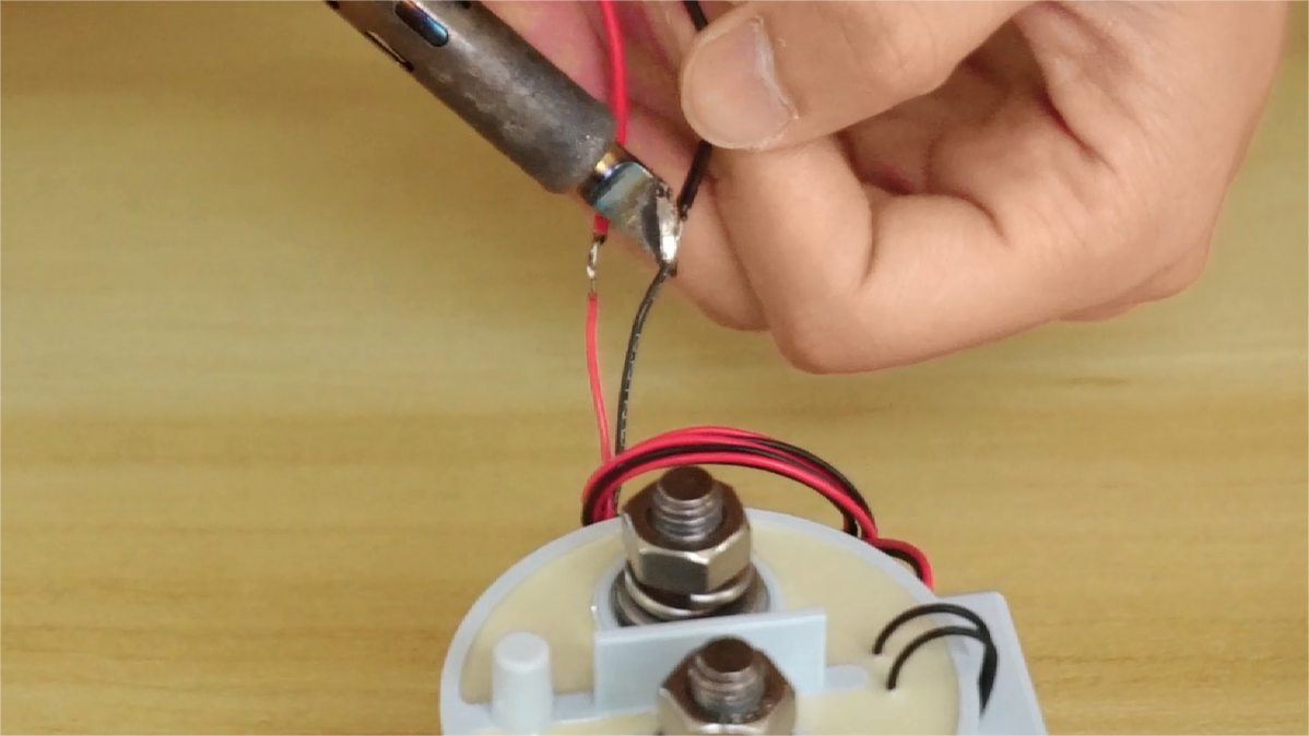
First:solder the 13P battery cable to the battery pack.
(12S slave boards can be used for 6S-12S batteries. If the battery is below the 12S specification, the wiring method is to short circuit the remaining blue power wire and the last red wire.)


And then test the battery voltage and Check the total voltage is consistent

1* PCBA MKBMS-LV Master Mini board V1.4
1* EVC500 Main Contactor
3* HY2.0 single head 2P wire
1* USB cable type-C data cable
4* 90° angle terminal block T90-25/8 (red copper)
4* M8 Copper Gasket (Red Copper)
1* 2.0MM jumper cap
Fixing bolts
1* DC-DC step-down power supply module12V
GH1.25 single head 5P wire
GH1.25 single head 2P wire
1* 1.3 inch OLED display LCD screen module
1* 12MM 3-6V key switch
GH1.25 double head 2P wire
GH1.25-5P to Dupont wire
Refer to detailed wiring diagram

Any switch or push button N.O. contact can be used. Common terminal from the switch should be connected to GND pin & N.O. to NO

MAXKGO master-slave board BMS require at minimum an external 12V power supply connected to the 12V connector input. The power supply must be powerful enough to supply the peak power required to close the main contactor and protected against short circuits
Warning: Make sure to respect the 12V power supply polarity on the 12V connector input. Power supply must be protected against short circuits.
The OLED display output is using I2C protocol and the driver output for SSD1306 display is standard in the firmware. Pinout on Master board should be connected according to the corresponding pins on the display. Any other I2C compatible display can in theory be used.
Many messages are shown on the display that can be helpful for troubleshooting or during main operation. Here is a list of displayed info:
Operation:
SOC
Pack voltage
Current
Pack temperature min
Pack temperature max
Pack temperature average
Precharge error
Global error/fault
Battery empty
Battery charged
YOLO mode
Charging:
SOC
Balancing:
SOC
USB, serial (UART) & CAN connectors are available and can be used for communication purposes. At the code level, an abstraction layer provide equal functionalities & messages to be sent and received on each connector. Messages are normally broadcasted on USB, UART simultaneously & can also be sent over CAN channel. The implementation of message is similar & will be compatible to VESC motor controllers in the future.
After completing all the wiring steps, we will get:
Connect the USB cable to the computer for parameter setting.
Open the ENNOID soft ware.
①Click "Connection"
②Click to refresh
③Click to connect
④Click "Cell Management"
 Fill in the relevant parameters according to the model of the slave board, the number of chips and the battery pack used.
 ⑤Select "12S-LTC6811" (Select according to the slave board model, and "15S-LTC6812" and "18S-LTC6813" are optional.)
⑥Choose the number of chips
⑦ Modify the number of batteries in series to 30 (If the battery specification is 20S, enter 20)
⑧Click to download the program
⑨Click Save
⑩ Disconnect parameter setting
Disconnect the USB connection after parameter setting.
Press the power button to power on.
The master-slave board BMS installation is complete.
Thank you for your patience in reading, see you in the next blog.


