MAXKGO master-slave board BMS with 2 Contactors Installation Tutorial & Charging Test
, by MAXKGO COMPANY, 3 min reading time

, by MAXKGO COMPANY, 3 min reading time
Hi, guy. Welcome to this blog. This blog will introduce the complete installation process of MAXKGO master-slave board BMS and 2 Contactors.
We also made a vedio about this blog. After you watch it, consider subscribing to the MAXKGO channel for more BMS videos.
Here is the video link: https://youtu.be/lHyuqA7qm9c
For this installation we use:

1 * Step-down Power Supply Module 12V
These 5 main products and related components
We used a 12S battery pack for this installation.
In this operation, we used XT90 and 90° Block Copper Terminal to assemble the cable.
1. Battery pack connect cable-used to connect the battery pack-Master Mini Board and Contactor 2.Output cable-used to connect BMS and output devices (such as ESC)
3. Charging cable - used to connect the power supply and BMS
*Weld the negative end of the charging cable and the output cable to the same terminal
4. Contactor connect cable-used to connect the contactor-1 and contactor-2

Solder GH1.25 single head 2P line to the Contactor-1
Solder HY2.0 single head 2P line to the Contactor-2
Refer to detailed wiring diagram

1. Connect Contactor-2 (with HY2.0 single head 2P line) to the Master Board
2. Fix the positive end of the Battery pack connect cable and the Contactor connect cable to the BAT+ port of the master board.

3. Fix the negative end of the Battery pack connect cable to the BAT- port of the master board. 
4. Connect the HY2.0 line on Contactor-2 to the Discharge port of the Master Board
5. Fix the other end of the Contactor connect cable to the negative end (A2) of Contactor-1

6. Connect the GH1.25 line on Contactor-1 to the Charge port of the Master Board

7. Fix the negative end of Output cable and Charge cable to LOAD- port of the master board.

8. Solder a black silicone wire to the positive terminal of the charging wire

9. Fix the positive end of the Charger cable to the positive end (A1) of Contactor-1

10. Fix the black silicone cable to the negative end of the CHARGE port of the Master Board

11. Fix the positive end of Output cable to LOAD+ port of the master board.
 12. Install the 12V step-down power module to the master board's 12V input and "BAT power to PSU" port.
13. Install 2.0MM jumper cap to "E-STOP" port of the master board.
14. Install OLED display LCD screen module to "OLED" port of the master board.
15. Install 12MM 3-6V key switch to “Button” port of the master board.
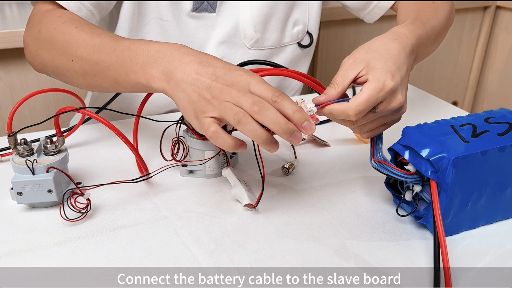
16.Connect slave board LTC6811-12S to Master Board's "ISOSPI" port.
Please refer to the wiring diagram below.

17. Connect the battery pack
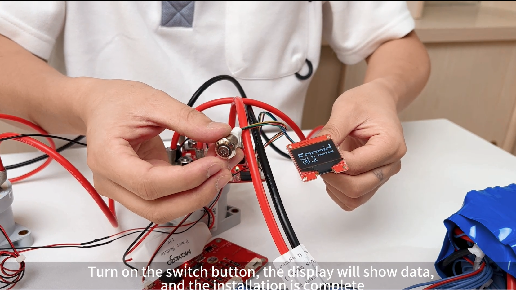
18. Turn on the switch button, the display will show data, and the installation is complete.
(Error 18 will appear when booting for the first time, which is a normal phenomenon. After the display goes off, press the power button to start the device normally.)
In the YouTube video, we conducted a charging test of the Battery, welcome to watch.
Thank you for your patience in reading, see you in the next blog.
Please follow our social media for more info, thanks.
YouTube: https://www.youtube.com/@MAXKGO
Instagram: https://www.instagram.com/maxkgo_share/
Facebook: https://www.facebook.com/MaxkgoMall


